MODEL MATCH
Check your motor
Read the nameplate and the supplied instructions. Confirm the motor configuration, control board and limit-switch type before installation.

Mount the base, align the gear rack, set the limits and check the system. Follow a clear installation sequence based on the supplied DCK series user manual.
For qualified installers. Based on the DCK156D–DCK196D and DCK200 manual. Always match the instructions to your motor and control board.

Read the nameplate and the supplied instructions. Confirm the motor configuration, control board and limit-switch type before installation.
Verify smooth manual travel, the planned base position and the rack path. Identify trapping points and keep the complete travel area clear.
A qualified technician must confirm supply requirements, grounding, leakage protection and short-circuit protection for the equipment and local rules.
Safety first: Isolate power before wiring, mechanical adjustment or maintenance. Secure the gate against unintended movement, keep children and other people away, and never bypass safety devices. This page is not a substitute for the supplied manual or professional commissioning.
Complete the mechanical installation before electrical checks and controlled commissioning.
Do not treat Fig. 1 dimensions as universal foundation dimensions for every model.
Foundation details and tightening requirements must be confirmed for the actual equipment and site.
The gate must not rest its full weight on the motor gear. Obtain the correct model-specific clearance; no universal rack gap is specified here.
Figs. 3 and 4 illustrate different housings, not separate release and engagement stages. Verify key direction on your actual unit.
Install the bracket on the rack according to the required final travel positions. Use the limit type fitted to your motor; these are alternatives, not two devices required on every unit.
Point the magnet toward the motor and position it relative to the magnetic limit switch inside the housing. Verify the arrangement and clearance in the supplied instructions.
Position the switch flapper so that it contacts and correctly operates the spring switch at the required travel position. Do not allow overtravel or mechanical impact.
Match the wiring diagram to the motor and control-board version before making connections. Fig. 7 shows the manual’s motor and limit-switch reference; it does not establish every safety-device or mains-input terminal.
Power isolated. Qualified personnel only. Do not connect by wire colour alone or assume this diagram applies to a different board. Ask OMKER if the actual terminal labels do not match.
Testing is a controlled task for the qualified installer. Keep the travel zone closed to people and vehicles.
Check supply data, grounding, wiring and mechanical mounting. Remove obstructions from the travel area.
With power isolated, release the drive and verify smooth manual movement. Re-engage as specified before powered testing.
Follow the model-specific trial-run procedure. Observe the gate and stop immediately if motion is abnormal.
Isolate power before repositioning limit components. Repeat controlled tests and verify final open and close positions.
Stop if anything is unexpected. Review the installation and matching manual before continuing. Controller learning, remote pairing and force settings require the relevant control-board instructions and are not specified by this guide.
Use this as a handover record, not a replacement for a safety assessment or model-specific commissioning requirements.
The lockable release permits manual gate movement during a power outage. Isolate power, secure the gate, and follow your model’s key instructions. Re-engage the drive before powered operation.
Review the release diagrams ↗Disconnect power before maintenance. Check grounding, mountings and component condition. Follow the supplied manual for lubrication; do not add or replace internal lubricant based on generic advice.
The supplied manual states that its internal lubricant does not require replacement or replenishment. Confirm applicability to your exact unit.
DCK-156D Series Sliding Gate Motor User Manual · 7 pages · PDF
Installation figures, manual release, motor/limit wiring, trial-run instructions and maintenance notes in the document supplied for this guide.
Compare the cover model list with the equipment delivered. The instructions supplied with your motor and control board take priority if versions differ.
Use the product page to identify the motor, then confirm the exact manual and control-board version with OMKER. Product listings may include variants outside this guide.

Listed DCK sliding gate motor variants. Match the nameplate before following this guide.
View Product Details ↗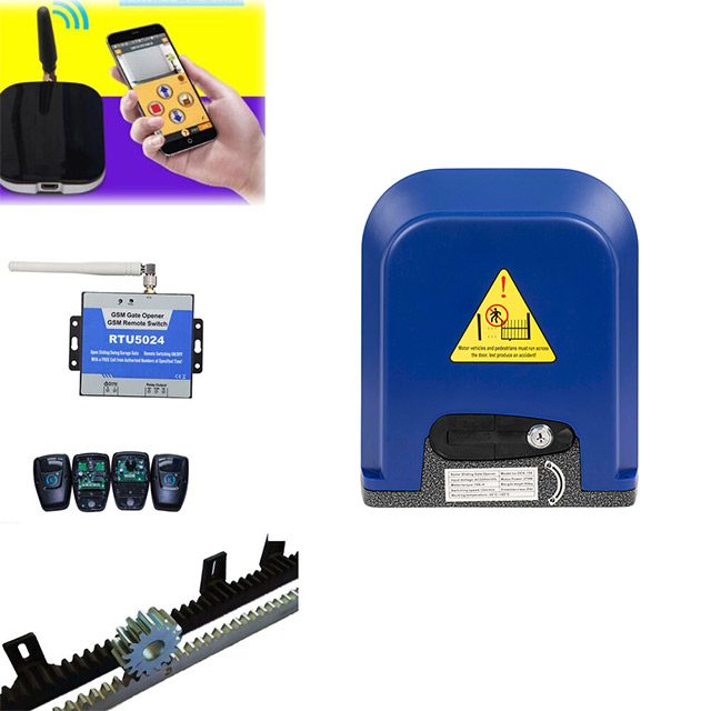
Confirm the supplied configuration and installation instructions for your order.
View Product Details ↗Send your motor model, control-board model, a clear photo of the terminal labels and a description of the installation question. Keep power isolated while an unresolved wiring or mechanical issue is being reviewed.
Include the relevant manual figure and photos of your actual setup. Do not continue testing a gate that moves unexpectedly.
