
Views: 0 Author: Site Editor Publish Time: 2026-11-10 Origin: Site


| Section | Summary |
|---|---|
| 1. Straight Arm Barrier Gate: A Classic Choice | Explains the standard horizontal arm design, suitable lane widths, operating limits and integration requirements. |
| 2. Articulated Arm Barrier Gate: Flexible Adaptation | Shows how a hinged arm reduces the swept height and helps installations with low ceilings or limited clearance. |
| 3. Fence Barrier Gate: Enhanced Security | Examines full width physical closure for sites that need stronger pedestrian and vehicle exclusion. |
| 4. Advertising Barrier Gate: Creativity and Revenue | Describes how a visible arm surface can support wayfinding, sponsorship or commercial messaging without weakening safety. |
| Important Considerations When Choosing a Barrier Gate Type | Provides a selection framework covering compatibility, durability, safety, maintenance, appearance and scalability. |
A straight arm barrier gate uses a rigid horizontal rod that rotates upward and downward from a motorized cabinet. It is the most familiar layout for parking lots, apartment entrances, commercial buildings, toll access points and factory yards. The arm creates a clear visual signal and a physical control point without occupying the full lane when it is raised.
Its simple geometry makes the straight arm barrier gate comparatively easy to specify. The main variables are lane width, arm length, cabinet position, counterbalance spring, opening time and the traffic control interface. A standard rod is often selected for a clear lane, while longer arms require correct spring placement and careful adjustment so the motor is not forced to carry an unbalanced load.
The supplied control manual identifies a JL 601 barrier platform with AC 220 V plus or minus 15 V input, 50 or 60 Hz frequency, 280 W power, a 5 to 6 second starting time and standard straight rods from 3 m to 6 m. It also specifies spring positions for different rod lengths: hole one for 5.5 to 6 m, hole two for 4.5 to 5.5 m and hole three for 3 to 4.5 m. These values show why the arm, spring and motor should be ordered as a matched assembly.
| Parameter | Manual reference | Selection meaning |
|---|---|---|
| Power supply | AC 220 V ±15 V, 50 or 60 Hz | Confirm site voltage, frequency, earthing and protective device. |
| Motor power | 280 W | Use with the specified mechanism and duty conditions. |
| Starting time | Approximately 5 to 6 seconds | Useful for estimating queue capacity and traffic flow. |
| Standard rod length | 3 m to 6 m | Choose by clear lane width and safe end clearance. |
| Operating temperature | Minus 40 to plus 70 degrees Celsius | Check whether the site climate and enclosure installation match. |
For a conventional car park, a straight arm barrier gate is normally the first design to evaluate because its movement is easy for drivers and cameras to interpret. Buyers can review a complete automatic parking barrier gate system when they need a coordinated cabinet, arm, controller and vehicle access interface rather than a motor alone.
An articulated arm barrier gate uses a hinged joint so the arm folds as it rises. This reduces the vertical clearance needed above the cabinet and can make the design suitable for underground garages, buildings with low beams or entrances close to ceilings. The horizontal section still controls the lane, but the joint changes the movement envelope during opening.
The articulated design requires more mechanical coordination than a straight arm. The hinge, linkage, stop position, counterbalance and control limit must work together. A purchaser should ask for the folded height, maximum lane width, hinge service method and the recommended adjustment procedure. If the hinge is loose or the arm is not balanced, the gate can stop short of its intended position or create impact at the end of travel.
In a parking management system, the same access logic can be used as with a straight arm. RFID readers, ticket dispensers, license plate recognition, loop detectors and photoelectric sensors can send open or close commands. The difference is mechanical clearance. I normally request a drawing showing the cabinet, pivot, raised arm, lowered arm and nearby structures before approving the layout.
| Design point | Why it matters | Buyer question |
|---|---|---|
| Hinge assembly | Transfers movement between arm sections. | Is the joint protected and serviceable? |
| Folded height | Determines fit under beams and ceilings. | What is the maximum raised profile? |
| Counterbalance | Reduces load on the motor and linkage. | How is the spring adjusted for the arm length? |
| Limit control | Stops the arm at the intended open and closed angles. | Are photoelectric or mechanical limits used? |
An articulated barrier gate is not automatically better for every site. It may add components and maintenance points, so it should be selected when the clearance benefit solves a real installation constraint. Where there is adequate overhead space, a straight arm can provide a simpler mechanism and easier visual inspection.
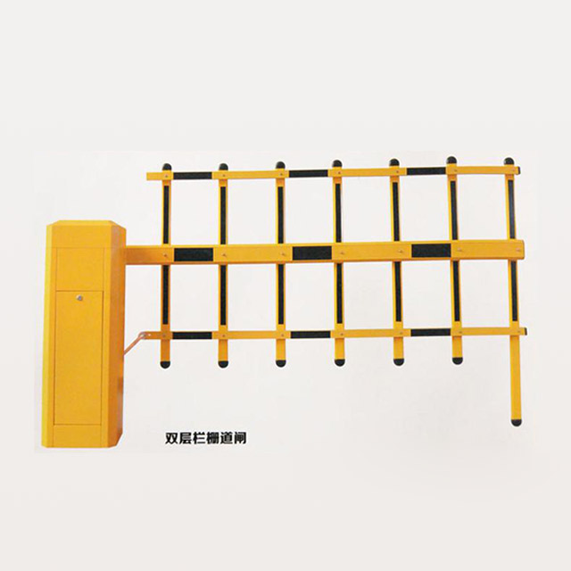
A fence barrier gate adds a vertical or mesh barrier to the moving arm so the opening is harder to bypass. It is used where a simple horizontal rod does not provide enough physical deterrence, such as restricted industrial yards, logistics facilities, utility compounds and controlled service roads. The design can help discourage pedestrians from walking around the end of a short arm. For sites combining vehicle screening with automated access records, a vehicle access barrier solution can be evaluated together with the fence geometry and lane safety devices.
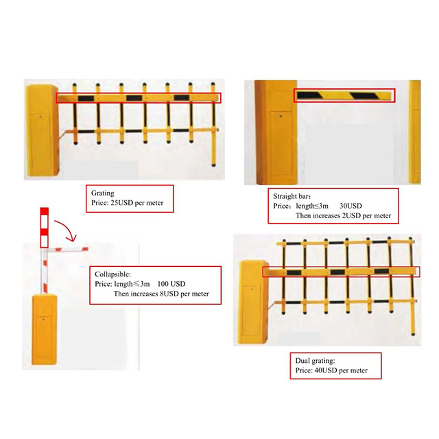
The additional fence area increases wind load, weight and visual obstruction. This affects the cabinet foundation, counterbalance spring, motor torque and stopping behavior. A fence barrier gate should therefore be engineered as a complete mechanical package. The supplier should state the maximum arm length, fence dimensions, wind assumptions and recommended foundation details.
Security must still be balanced with emergency access. The system should provide a manual release or rocker mechanism that allows the arm to be raised when power is unavailable, subject to site procedures. The manual specifies a rocker for raising or lowering the rod by hand when power is off. It also warns that nonprofessionals should not operate the equipment and that people or vehicles must not remain beneath the arm while it is moving.
| Risk or load | Effect on selection | Control measure |
|---|---|---|
| Wind pressure | Increases arm and cabinet load. | Use a rated fence area and anchored foundation. |
| Added mass | Changes balance and motor demand. | Set springs for the actual assembly. |
| Pedestrian bypass | Requires stronger side closure. | Combine fence geometry with access control and signage. |
| Power failure | Can block emergency movement. | Provide trained manual release procedures. |
An advertising barrier gate adds a printable or highly visible surface to the arm so the access point can carry wayfinding, sponsor identity or commercial messaging. It is particularly useful in retail car parks, shopping centers, hotels, airports and event venues where drivers already pause at the entrance.

The message should remain secondary to safe operation. Text and graphics must be visible from the driver's approach, while reflective colors, warning markings and lighting should not be covered. Additional panels can alter wind area and mass, so the advertising material should be approved with the barrier manufacturer. A lightweight, weather resistant finish is generally easier to balance than a heavy signboard.
For B2B buyers, the useful question is not simply how much advertising space is available. It is whether the arm remains visible at night, whether the printed surface can be replaced, and whether the extra load changes the opening time or spring setting. The control system should still support reliable limit detection, loop input, photoelectric protection and a safe stop command.
| Advertising design point | Technical requirement | Operational reason |
|---|---|---|
| Panel weight | Stay within the approved arm load. | Protects motor, spring and hinge life. |
| Weather resistance | Use materials suitable for UV and rain. | Preserves legibility and appearance. |
| Visibility | Keep warning marks and lights unobstructed. | Supports driver recognition and safety. |
| Replacement method | Allow panels or films to be changed without dismantling the arm. | Reduces downtime for campaigns. |
Compatibility means more than matching voltage; it means the barrier gate, access reader, safety device, cabinet and site network must exchange the right signals. Confirm the power supply, relay inputs, loop detector, photoelectric sensor, remote transmitter, license plate platform and building management interface. The manual describes emitter learning and cancellation procedures, which should be documented for commissioning and service staff.
Also check mechanical compatibility. The cabinet foundation, arm length, spring hole and limit target must correspond to the selected configuration. A 6 m rod installed with a spring position intended for a shorter rod can create unstable movement and poor stopping accuracy.
Durability depends on traffic cycles, temperature, rain, dust, corrosion and impact exposure. The manual lists a working temperature from minus 40 to plus 70 degrees Celsius and requires protection from rainwater submerging the barrier during installation. Ask for cabinet material, coating, sealing, motor duty information and replacement parts before purchase.
High traffic sites should compare cycle capacity and opening time rather than selecting by motor wattage alone. A robust barrier gate still needs a correctly anchored cabinet, tight arm connections and an adjusted counterbalance.
Safety devices should prevent the arm from closing onto a vehicle or person and should support controlled stopping at open and closed limits. The manual describes a sensitive photoelectric limit control system and optional sense coil detector functions for automatic closing after a vehicle passes, collision prevention or automatic raising when the barrier is broken.
Commissioning should include loop detection, photocell alignment, emergency stop behavior, manual release and power recovery. The installation area should have clear markings and no standing position directly beneath the moving arm.
Maintenance cost includes inspection time, replacement parts, access equipment and lost lane availability. The manual specifically notes that the mechanism uses high quality antifreeze lubricating grease and instructs users not to replace it or add lubricating oil. This is a useful example of why service teams should follow the supplied lubricant specification instead of applying a general oil.
Routine checks should cover fixing bolts, arm connection screws, spring condition, limit targets, photoelectric alignment, emitter operation and cabinet earthing. Fault diagnosis should start with the power supply, fuse, capacitor connection, motor condition and rod installation before adjusting the control board.
Appearance matters in hotels, offices, retail developments and residential projects. The cabinet and arm should fit the entrance architecture, but visual design must not hide warning stripes, lights or the arm's moving edge. Advertising arms require extra review because graphics and panels can change visibility and balance.
A scalable barrier gate system can add lanes, readers, cameras, tickets or remote monitoring without replacing every cabinet. I recommend defining the future access logic before choosing the first unit. A parking barrier gate platform for vehicle access management can be assessed by its control inputs, safety interfaces, service access and ability to operate consistently across multiple lanes.
| Selection factor | Questions for procurement | Evidence to request |
|---|---|---|
| Compatibility | Which readers, loops and controllers can connect? | Wiring diagram and interface list. |
| Durability | What climate and traffic cycle are supported? | Operating range and duty data. |
| Safety | How does the barrier detect an obstruction? | Sensor arrangement and commissioning procedure. |
| Maintenance | Which parts and lubricants are specified? | Manual, spare parts list and service intervals. |
| Scalability | Can additional lanes and access devices be integrated? | Control protocol and system architecture. |
Select a barrier gate type by matching its mechanical movement to the site geometry and its control system to the parking operation. Straight arm barriers cover standard lanes, articulated arms address low clearance, fence barriers increase physical exclusion and advertising barriers add a communication surface. Each design still requires correct spring balance, limit control, safe detection, emergency release and regular inspection.
Before ordering, confirm the lane width, arm length, power supply, climate, traffic cycle, foundation, safety sensors and integration points. For the JL 601 reference system, the manual identifies AC 220 V plus or minus 15 V, 280 W power, 5 to 6 second starting time, 3 to 6 m standard rods and a minus 40 to plus 70 degree Celsius working range. These figures should be verified against the exact configuration and local installation conditions.
Buyer checklist: select the arm type, calculate the clear opening, match the spring position, verify motor and controller ratings, specify photoelectric and loop protection, document manual release procedures, and request a complete wiring and maintenance package before installation.
